7 Common PCB Prototype Assembly Problems and How to Prevent Them
Direct answer: Common prototype PCB assembly failures usually begin with an unverified footprint, ambiguous polarity, inconsistent BOM and placement data, an uncontrolled solder process, inspection that cannot see hidden joints, or unsafe first-power troubleshooting. Prevention starts before release and preserves evidence when a defect appears.
What decision does this guide support?
This guide links seven recurring prototype problems to the checks that can prevent or contain them. It helps engineers distinguish a visible symptom from the design, data, material, process, or test cause that created it.
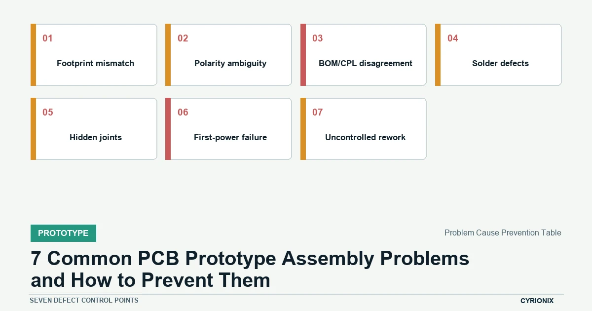
Problem Cause Prevention Table
Use the table during design release, assembly planning, and failure review. Do not continue when the suspected cause cannot be separated from the symptom or when rework would erase the evidence.
| Control point | Required action or evidence | Hold condition |
|---|---|---|
| Footprint mismatch | Verify land pattern, package code, pin numbering, and body clearance. | The selected part cannot be traced to an approved footprint review. |
| Polarity ambiguity | Put unambiguous marks on fabrication and assembly documentation. | Diode, LED, capacitor, or IC orientation remains interpretive. |
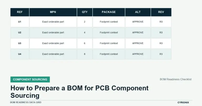
| BOM/CPL disagreement | Run a reference-designator reconciliation across BOM and placement data. | Population lists differ by reference or variant. |
| Solder defects | Review stencil, paste, placement, pad geometry, and thermal balance together. | The suspected cause has not been separated from the visible symptom. |
| Hidden joints | Identify BGA, QFN, and bottom-terminated devices before quoting inspection. | Acceptance relies only on a view that cannot reveal the joint. |
| First-power failure | Use current limits and staged rail/interface checks before full function. | The failure state is not reproducible or safely bounded. |
| Uncontrolled rework | Record defect, action, operator instruction, and post-rework verification. | The modified board no longer has a traceable condition. |
Footprint and package mismatch
Verify the land pattern against the exact manufacturer package, pin numbering, body dimensions, courtyard, and assembly orientation. Similar package names do not guarantee identical pads or pin assignments.
Polarity ambiguity
Use unambiguous board markings and assembly drawings for diodes, LEDs, electrolytic capacitors, connectors, and IC pin one. Check that markings remain visible and interpretable after parts are placed.
BOM/CPL disagreement
Reconcile reference designators, fitted status, quantity, variant, and package across the BOM and CPL. A placement file can be syntactically valid while describing a different population from the purchasing list.
Solder bridging and insufficient solder
Review stencil aperture, paste deposition, placement, pad geometry, thermal balance, and reflow conditions together. The observed bridge or open joint is evidence, not by itself proof of the root cause.
Hidden-joint inspection limits
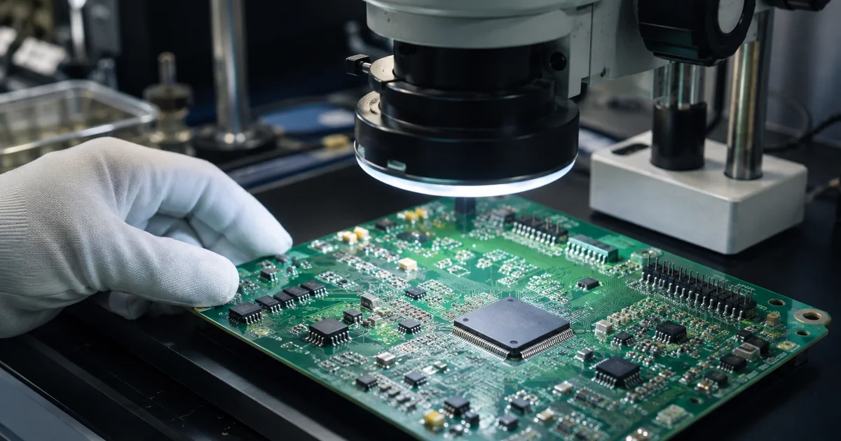
Identify BGA, QFN, and bottom-terminated devices before quotation and choose inspection or functional evidence suited to their risk. Optical inspection cannot confirm a joint that the camera cannot see.
First-power failures
Apply current limits and check rails in stages before attempting full function. Record voltages, current, temperature, programmed state, and the exact failure sequence so the condition can be reproduced safely.
Prevention table
Include controlled rework in the prevention plan. Record the defect, action, affected reference, instruction, and post-rework verification so the modified board still has a traceable condition.
Use failures to improve the next release
- Preserve the initial evidence. Photograph and identify the board before cleaning or rework.
- Separate symptom from cause. Check design data, material, setup, process, and test assumptions.
- Feed back the control. Update the released package or build instruction, not only the repaired unit.
Related Cyrionix resources
Continue with the prototype PCB assembly service and pre-power quality-check guide before the next build.