
PCBA Prototyping: From Design Files to a Working Assembly
A practical workflow for moving from released design outputs through sourcing, assembly, inspection and engineering validation.
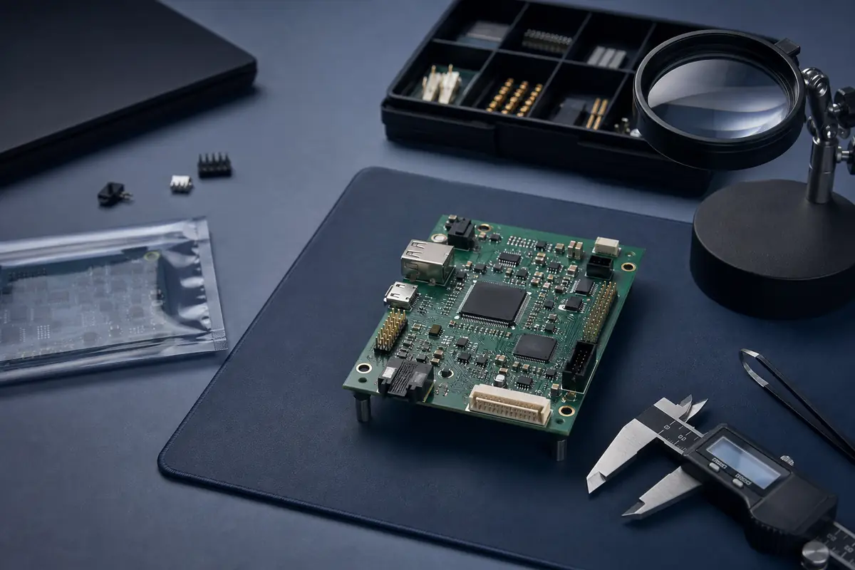
PCBA prototyping is the controlled process of turning PCB fabrication data, a BOM and placement information into a small number of assembled boards for engineering validation. A useful prototype is not only a physical board: it also produces documented sourcing decisions, manufacturing feedback, test results and revision changes for the next build.
The PCBA prototype workflow
| Stage | Input | Useful output |
|---|---|---|
| 1. Objective | Questions the build must answer | Validation plan and acceptance criteria |
| 2. Data review | Gerber, BOM, CPL, drawings | Resolved revision and data issues |
| 3. Sourcing review | Exact MPNs and approved alternatives | Purchasing plan and exception list |
| 4. Manufacturing planning | Board and assembly requirements | Confirmed process scope and quotation |
| 5. Build | Released package and materials | Assembled prototype boards |
| 6. Verification | Inspection, programming and test instructions | Recorded results and open issues |
| 7. Next revision | Build feedback | Updated design or low-volume release |
Three review gates
Data gate
All manufacturing files should identify the same revision. DNP status, polarity, board side and reference designators need consistent treatment across the BOM, placement file and assembly drawing.
Material gate
Every purchased line needs an exact part identity or a controlled approval path. Availability, MOQ, packaging, lifecycle and substitutions can affect both timing and technical risk.
Validation gate
Programming and functional behavior cannot be inferred from Gerber data. Provide firmware, interfaces, fixtures, expected results and acceptance limits when those steps are required.
Standards context
IPC describes J-STD-001 as the electronics-industry standard for soldering process and material requirements, while IPC-A-610 provides post-assembly acceptance criteria. A project should specify any required revision and class; the existence of a standard does not prove that Cyrionix or every manufacturing partner is certified to it.
Questions to resolve before release
- What must this prototype prove?
- Which file revision is released?
- Who approves substitutions?
- Which parts are consigned?
- What inspection, programming and test steps are required?
- What feedback must be retained for the next build?
From prototype to controlled low volume
| Stage | Decision to close | Typical evidence | Next gate |
|---|---|---|---|
| Prototype | Can the released design be assembled and brought up? | Revision-controlled files, build notes, inspection and initial test results | Engineering issues are dispositioned |
| Validation | Does the product meet the defined engineering requirements? | Controlled firmware, measurements, functional results and issue log | Design and test criteria are stable enough for a pilot |
| Pilot / first article | Did the manufacturing setup produce an acceptable first result? | First-article identity, workmanship, programming/test evidence and deviations | Authorized release of the remaining batch |
| Controlled low volume | Can the same revision, materials and controls be repeated with traceable changes? | Travelers, material records, result logs, change control and reconciliation | Production transfer or the next controlled build |
Continue your project planning
Use the related service and resource pages to turn this guidance into a reviewable manufacturing request.
Related decision guides
Use these focused resources before releasing the next assembly package.