
PCB Design for Manufacturability (DFM): What to Check Before Assembly
Check whether the design and released manufacturing data can be built, inspected and tested using a confirmed process without hidden assumptions.
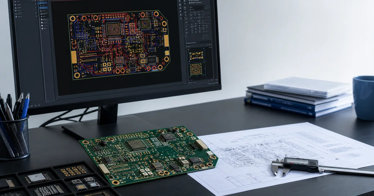
PCB DFM is a pre-release review of design features, component data, assembly access, test access and manufacturing documentation. It does not replace electrical verification or a selected manufacturer's process rules. The useful outcome is a resolved issue list and one consistent release package, not a generic pass label.
Pre-Assembly DFM Checklist
| Review area | Question to close | Evidence | Hold condition |
|---|---|---|---|
| Footprints and packages | Do land patterns, pin numbering and package variants match the ordered parts? | Library source, datasheet and BOM mapping | Package or pin identity is ambiguous |
| Orientation and polarity | Do CAD data, assembly drawing and physical markings agree? | CPL, drawing and part documentation | Two files show different orientation |
| BOM consistency | Are designators, quantities, DNP state and MPNs complete? | Released BOM and schematic/design database | A fitted designator has no controlled part identity |
| Gerber and drill consistency | Do fabrication outputs represent the same released board? | Output package, layer map and revision | Layer, outline or revision cannot be confirmed |
| CPL / placement consistency | Do coordinates, side, rotation and origins match the fabrication data? | Placement export and assembly view | Origin or board side is unresolved |
| Assembly access | Can components be placed, soldered, inspected and reworked under the chosen process? | Layout review and partner feedback | Critical access depends on an unconfirmed process |
| Test access | Can required nets, rails and interfaces be reached safely? | Testpoint rules, reports and fixture concept | The required measurement has no access path |
| Panel and handling context | Are board support, edge features and separation assumptions confirmed? | Partner-specific panel proposal | A universal panel rule is being assumed |
| Manufacturing notes | Are special materials, handling, soldering and acceptance needs explicit? | Fabrication/assembly drawings and notes | A critical requirement exists only in email context |
What DFM should not become
A DFM guide should not publish one spacing, stencil, panel or testpoint value as universal. Package construction, board stack-up, assembly process, fixture access and partner capability change the valid limits. Use EDA rules and datasheets to find issues, then resolve process-specific questions with the selected manufacturing resource.
Release gate
- Gerber, drill, BOM, CPL and drawings identify one revision.
- DNP, polarity, connector orientation and special handling are explicit.
- Component substitutions have a named engineering approval owner.
- Programming and test access are defined before fixture or process decisions.
- Open DFM issues have an owner, disposition and release decision.
Technical sources
Continue the decision path
Continue with the related service and engineering guides for the current build stage.
When the released package needs a project-specific commercial review, continue to the PCB DFM Review service. The service page defines inputs, review boundaries and the decision record used before quotation or manufacturing release.
Need a project-specific review?
Share the released files, BOM, quantity, open decisions and required verification scope.