How to Review PCB Panelization for Assembly
Before approving a PCB panel, check how it will move through fabrication, solder-paste printing, placement, soldering, inspection and depanelization. An efficient board arrangement still needs suitable grip areas, alignment features and support. Have both the fabricator and assembler review the proposal before releasing it.
This guide is for reviewing that proposal. The PCB DFM guide covers the broader release checks; panel dimensions and process clearances still need confirmation against the actual equipment and board construction.
Confirm what the panel contains
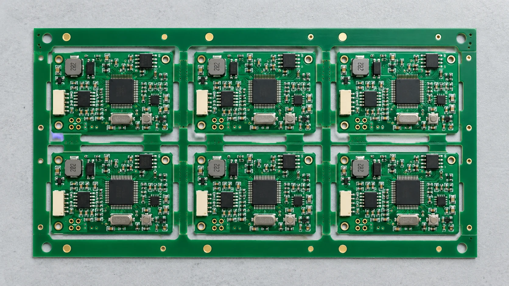
Record the board revision, array count, orientation of each board and overall panel dimensions. Confirm whether the drawing shows the assembly array delivered to the assembler or a larger fabrication working panel that will be cut down first. Review the dimensions of the array that will actually enter the assembly line.
Check whether placement data describes one board with a repeat pattern or the whole array. Establish the panel origin and how board positions are identified in inspection and test records. If different designs or variants share an array, their identities and material requirements must remain distinguishable through every operation.
Check rail, fiducial and support locations
Confirm which edges the equipment grips and whether populated components overhang those edges. Rails, tooling holes and fiducials should be usable at the operations that need them. A feature hidden by a clamp or a tall connector does not provide the intended reference.
Ask how the panel will be supported during printing and placement, especially where routed openings or heavy components reduce stiffness. Consider the bottom side as well as the top; a support point must not load a fragile component or short exposed contacts. Do not copy another project’s rail width or fiducial arrangement without checking the receiving line.
Screaming Circuits discusses how panel needs change between prototype and production. Recheck the panel when the assembly route or equipment changes, even if the single-board design stays the same.
Choose the separation method before freezing edge placement
V-scoring can suit layouts with appropriate straight separation lines. Routed profiles with connecting tabs can suit other geometries. Neither option is automatically gentler or cheaper for every board. Review the remaining material, board thickness, separation equipment and component clearances together.
Pay particular attention to ceramic components, connectors and solder joints near the separation path. Ask how the board is supported, where force is applied during depanelization and whether the tooling can reach without hitting parts. Agree on component clearance and strain limits for that design and process.
Use a panel approval record
Record the answers to these questions with the approved panel drawing.
| Check | Evidence to request | Question to resolve before approval |
|---|---|---|
| Array identity | Dimensioned drawing with board and panel revisions | Does this match the released single-board outline? |
| Transport edges | Agreed grip areas and component keep-outs | Can clamps clear both sides of the populated panel? |
| Alignment | Fiducials, tooling references and coordinate convention | Can each relevant machine locate the intended pattern? |
| Support | Support locations or tooling proposal | Will unsupported areas deflect during processing? |
| Separation | Score/tab geometry, equipment and edge review | Can the tool separate the board without component interference? |
| Rejected positions | Agreed marking and machine-skip procedure | How will unusable board positions be excluded? |
Do not overlook rejected boards and panel changes
Agree whether panels containing rejected board positions are acceptable and how those positions are marked and skipped. A visible mark alone is not a complete instruction for paste printing, placement, inspection and test. Confirm how the good-unit quantity will be counted and delivered.
A change to array orientation, tab placement or overall panel size can affect stencil, machine program, support and separation tooling. Issue a revised panel drawing and identify which downstream files or fixtures need review. A new single-board revision should also trigger a check that the old panel proposal is still valid.
For example, an edge-mounted connector may obstruct a transport rail, block the separation tool or put its solder joints under excessive load. Identify the interference and record the agreed design or process change before ordering the panel.
A combined PCB fabrication and assembly review helps keep the panel proposal aligned with both manufacturing stages.
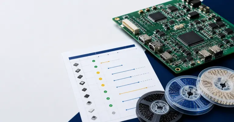
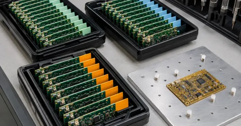
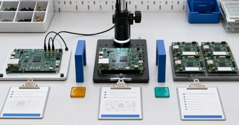
Cover image: AI-generated editorial illustration, not a production record or an acceptance reference.