How to Check PCB-to-Enclosure Fit Before Box Build
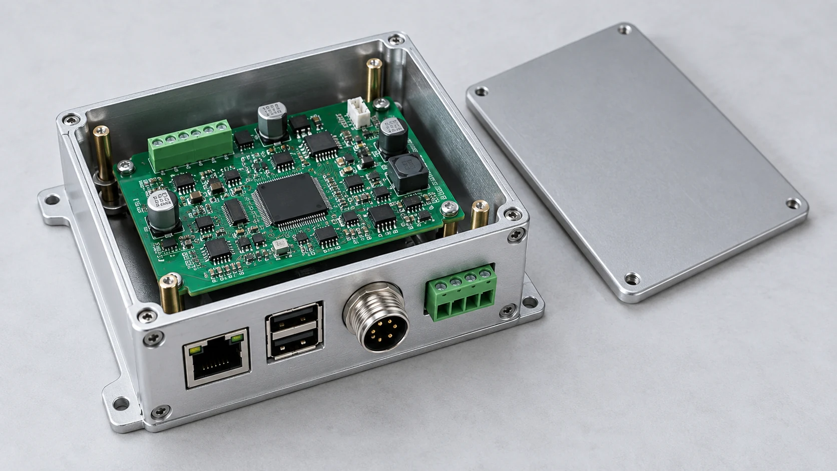
Check PCB-to-enclosure fit using the released board, populated component envelopes, enclosure and mounting hardware as one assembly. A matching board outline is only the first check. Connector mating space, screw access, wire routing and tolerance accumulation can stop a box build even when the bare PCB fits comfortably inside.
The design team is responsible for approving mechanical requirements and any changes. Use a box build assembly review to identify missing dimensions and installation conflicts before committing to a batch. Resolve those issues in the released drawings rather than leaving the assembly team to adjust parts to fit.
Align the ECAD and mechanical revisions
List the PCB revision, assembly configuration, enclosure drawing, lid, panel parts and hardware. Make sure the populated model represents the ordered configuration. An optional tall module can change the clearance even though the board outline and revision remain unchanged.
Establish shared datums and units before checking interference. Use the actual mounting surfaces and locating features, rather than aligning models visually until they appear to fit. Confirm that component models include relevant features such as connector latches, clips and overhanging bodies.
Altium’s ECAD-MCAD enclosure workflow describes checking the board and enclosure together. Compare library models with the specified parts: a simplified model may omit a latch or protrusion that interferes with the housing.
Review the mounting stack and tolerance chain
Check mounting-hole locations, hole clearances, support heights, screw engagement and board-to-metal separation. Include hardware and enclosure tolerances as well as PCB tolerances. Tightening a screw should not be the method for forcing a misaligned board into position.
Use the drawing’s approved tolerances to evaluate worst-case fit where appropriate. For example, a nominal lid clearance of 1.0 mm falls to 0.2 mm if the combined tolerance stack can reduce it by 0.8 mm. This illustrates the calculation, not a recommended clearance. The design engineer must establish the required minimum for the product.
Check connectors in both installed and mated states
A receptacle may align with a panel opening while its plug cannot enter fully. Include the mating plug, latch travel, cable exit and strain relief. Confirm which parts locate the connector and whether panel fastening imposes load on its solder joints.
For panel-mounted connectors connected by a harness, review the wiring route and service access. For board-mounted connectors, check the combined tolerances of the board mounts, connector position and panel cutout. A mismatch between these features can load the connector and its solder joints.
Walk through the assembly sequence
Identify the order of installation and the tool access needed at each step. A screw that is reachable before a harness is installed may become inaccessible afterward. A cable route that looks clear in the final model may require bending or pulling during installation.
Keep wiring away from sharp edges, pinch points and surfaces expected to become hot in operation. Follow the cable and connector manufacturers’ instructions for bend radius and retention. Include thermal interface pads and insulators in the fit check; their thickness can affect component loading and lid closure.
| Review area | Check in the released assembly | Record |
|---|---|---|
| Board location | Mounts, datums, holes and support heights | Drawing revisions and tolerance review |
| Component envelope | Top and bottom bodies, lid and housing clearance | Interference check and model limitations |
| Connections | Mating plug, latch, panel cutout and cable exit | Installed and mated checks |
| Installation | Tool path, sequence, wire routing and retained hardware | Work instruction and unresolved questions |
| First unit | Physical fit without unapproved modification | Photos, measurements and approved disposition |
Approve a physical first unit before repeating the build
Build the first unit with the specified parts and record connector mating, lid closure, board support and wiring condition. If parts need re-drilling, filing, unplanned shims or forced alignment to fit, stop and obtain approval for the deviation before continuing.
Mechanical fit does not establish electrical safety, EMC, environmental protection or functional acceptance. Those requirements need their own evidence. Define them alongside the agreed verification scope, and use a first-article release decision to authorize the repeat configuration.
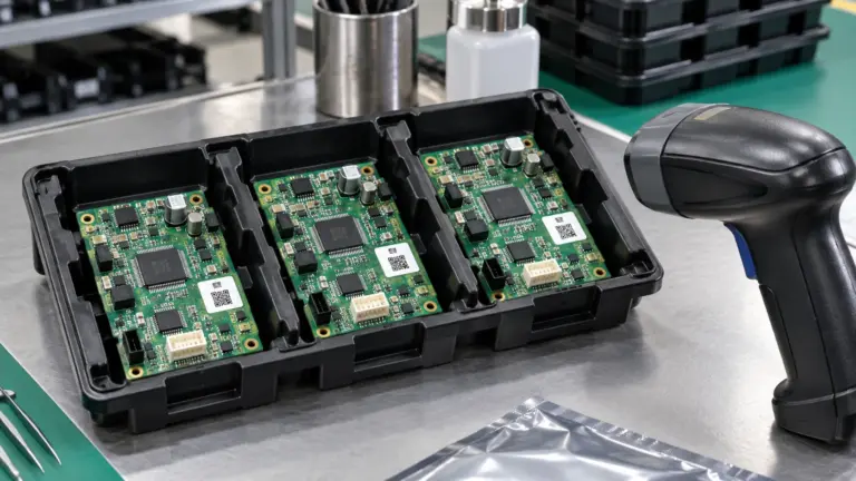
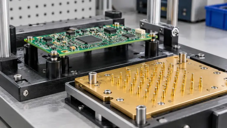
Cover image: AI-generated editorial illustration, not a production record or an acceptance reference.