Prototype PCB Assembly Quality Checks Before Functional Testing
Direct answer: Before applying power to a prototype PCBA, confirm board identity, inspect orientation and solder condition, check power rails against design expectations, and use a current-limited first-power procedure. Preserve evidence before rework so failures remain diagnosable.
What decision does this guide support?
This guide defines a staged check between assembly completion and functional testing. It helps engineers decide whether a board is safe and sufficiently understood to energize.
Inspection and Validation Workflow
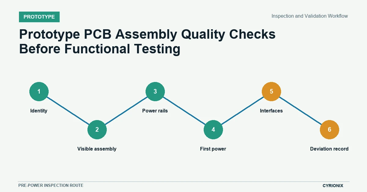
Move from identity to visible assembly, electrical screening, controlled power, interface access, and deviation records. A failed gate should pause the sequence until the reading or anomaly has an engineering disposition.
| Stage | Required output | Do not advance when |
|---|---|---|
| Identity | Match board marking, assembly revision, variant, and serialized record. | The received unit cannot be tied to the released baseline. |
| Visible assembly | Review polarity, orientation, solder condition, damage, and contamination. | A critical orientation or visible joint is doubtful. |
| Power rails | Check resistance or shorts using limits appropriate to the design. | A rail reading is unexplained or outside the engineering expectation. |
| First power | Use a controlled source and observe current against a defined ceiling. | Current rises unexpectedly or a device heats abnormally. |
| Interfaces | Confirm programming access, clocks, reset, and essential communications. | The board cannot be placed into a known test state. |
| Deviation record | Photograph, label, and disposition every anomaly before rework. | Rework would erase evidence needed for root-cause review. |
Confirm identity and revision
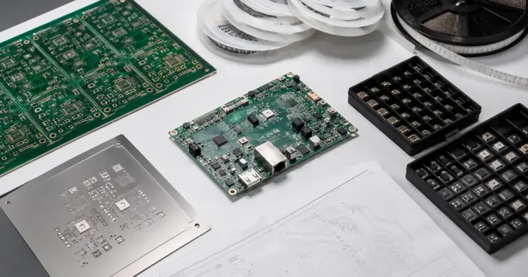
Match the board marking, assembly revision, variant, serial or lot record, and released build package. Do not troubleshoot a board until its hardware and programmed state can be tied to a known baseline.
Visual and polarity review
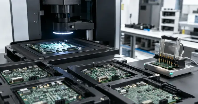
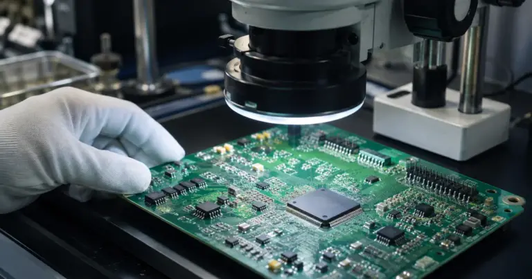
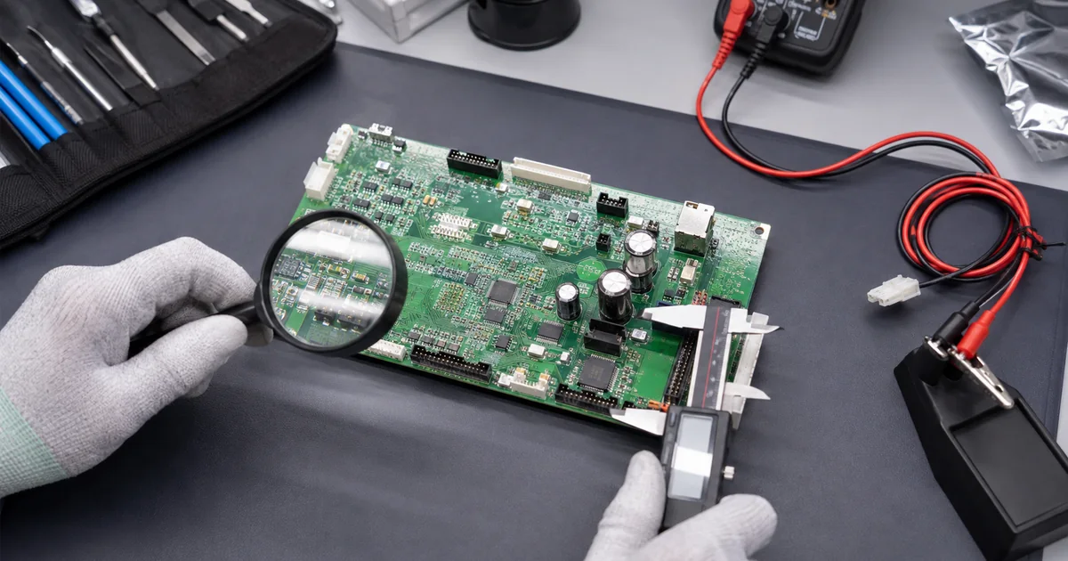
Inspect polarized components, pin-one orientation, solder joints, bridges, damage, contamination, and unpopulated positions against the approved variant. Magnification and viewing angle should match the features being assessed.
Short-circuit and rail checks
Measure resistance or diode behavior on critical rails using expectations defined by the design team. A low reading is not automatically a short, but an unexplained reading should be resolved before power is applied.
Controlled first power
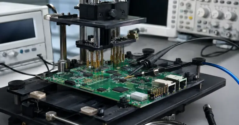
Use a suitable current-limited source, safe sequencing, and an agreed current ceiling. Observe rail voltages, total current, temperature, and obvious instability, and stop immediately when behavior departs from the plan.
Record deviations
Photograph and label anomalies before cleaning or rework changes the evidence. Record the affected reference, observation, decision, action, and verification result so root-cause review can separate design, material, and assembly causes.
Inspection workflow
The workflow is complete when the unit identity, visible condition, rail checks, first-power result, interface state, and deviations are recorded. Functional testing can then start from a known and recoverable condition.
Prepare a controlled first-power record
- Set expectations. List critical rails, normal resistance ranges, current ceiling, and shutdown conditions.
- Capture the initial state. Record identity and visible anomalies before rework.
- Advance in stages. Power only after each preceding check has a clear result.
Related Cyrionix resources
Continue with the prototype PCB assembly service and PCB assembly testing guide when defining acceptance evidence.