How Should a Prototype PCB Assembly Be Tested?
Direct answer: A prototype PCB assembly should be tested with the smallest set of methods that can detect the build risks and prove the intended engineering objective. Start with visual workmanship and assembly identity, add optical or X-ray inspection where the target joints require it, perform safe electrical checks, verify the loaded firmware, and run functional tests against written limits. No single method proves every defect category.
What decision does this guide support?
The purpose of prototype testing is to separate assembly defects from design, component, firmware, and fixture problems while the batch is still small enough to investigate. Select coverage from the failure modes that matter for this board, not from a generic list of equipment. Inspection capability and acceptance criteria must be confirmed with the selected manufacturing partner for the actual package mix.
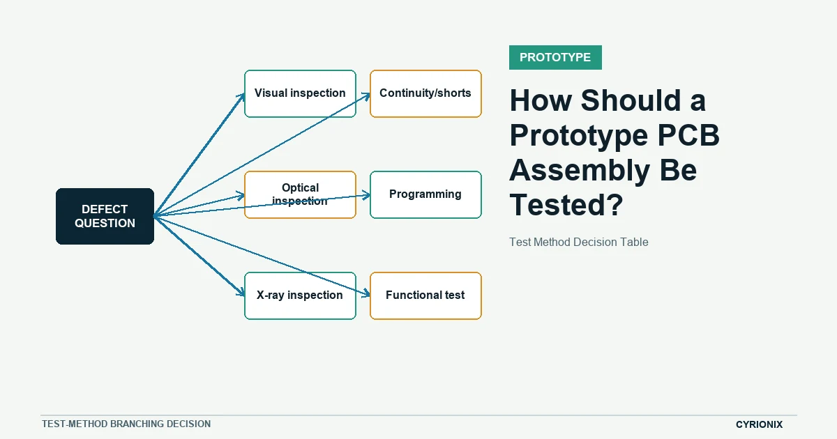
Prototype test-method decision table
The table maps each method to the question it can answer and the point where it should not be over-interpreted. Combine methods only when each closes a defined evidence gap.
| Decision factor | How to evaluate it | Stop condition |
|---|---|---|
| Visual inspection | Use for identity, orientation, workmanship, and visible solder conditions. | The target defect is hidden beneath a package. |
| Optical inspection | Use repeatable imaging when coverage and programming justify it. | A result is treated as proof of electrical function. |
| X-ray inspection | Consider for hidden joints and voiding questions with agreed criteria. | The image cannot be interpreted against an acceptance rule. |
| Continuity/shorts | Check nets or rails where safe access and expected values are defined. | The test can back-power or stress the design. |
| Programming | Verify image identity and read-back or functional evidence. | Binary revision and board revision are not linked. |
| Functional test | Exercise the product behavior, interfaces, loads, and limits that matter. | Pass/fail criteria or fixture responsibility is missing. |
Begin with the defect question
Write down what the team needs to learn: correct population, solder-joint integrity, absence of shorts, power-rail behavior, interface operation, sensor response, radio performance, or complete product function. Then identify which failures are visible, hidden, electrical, intermittent, or system-level. This avoids paying for inspection that cannot detect the failure of interest.
Use visual and optical inspection for assembly evidence
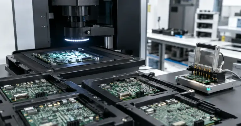
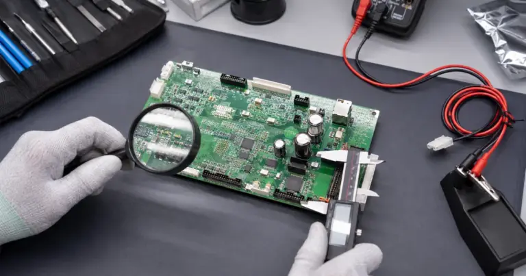
A controlled visual review can confirm board and component identity, orientation, obvious damage, contamination, solder bridges, and workmanship visible from the inspection angle. Automated optical inspection can improve repeatability and coverage when programming and image conditions are suitable. Neither method proves that a component is electrically correct or that hidden joints function.
Apply X-ray to specific hidden-joint risks
X-ray can provide evidence for BGA and other bottom-terminated joints, voiding questions, or internal connections that cannot be seen optically. The inspection plan should identify the locations, image views, sample size, and acceptance rule. An image without an agreed interpretation criterion is data, not a pass decision.
Plan continuity and power checks to avoid damage
Before full power-up, teams may check resistance to ground, critical net continuity, shorts, rail sequencing, or current-limited startup. Expected values and safe test points must come from the design owner. A generic continuity sweep can back-power circuits or create misleading results when semiconductor paths are present.
Control firmware programming and verification
Record the binary identifier, target hardware revision, programmer and settings, security configuration, serial-number rule, and verification result. Read-back, checksum, or a defined functional response can provide evidence, depending on the device. A board that boots is not proof that the intended production image was loaded.
Define functional acceptance in measurable terms
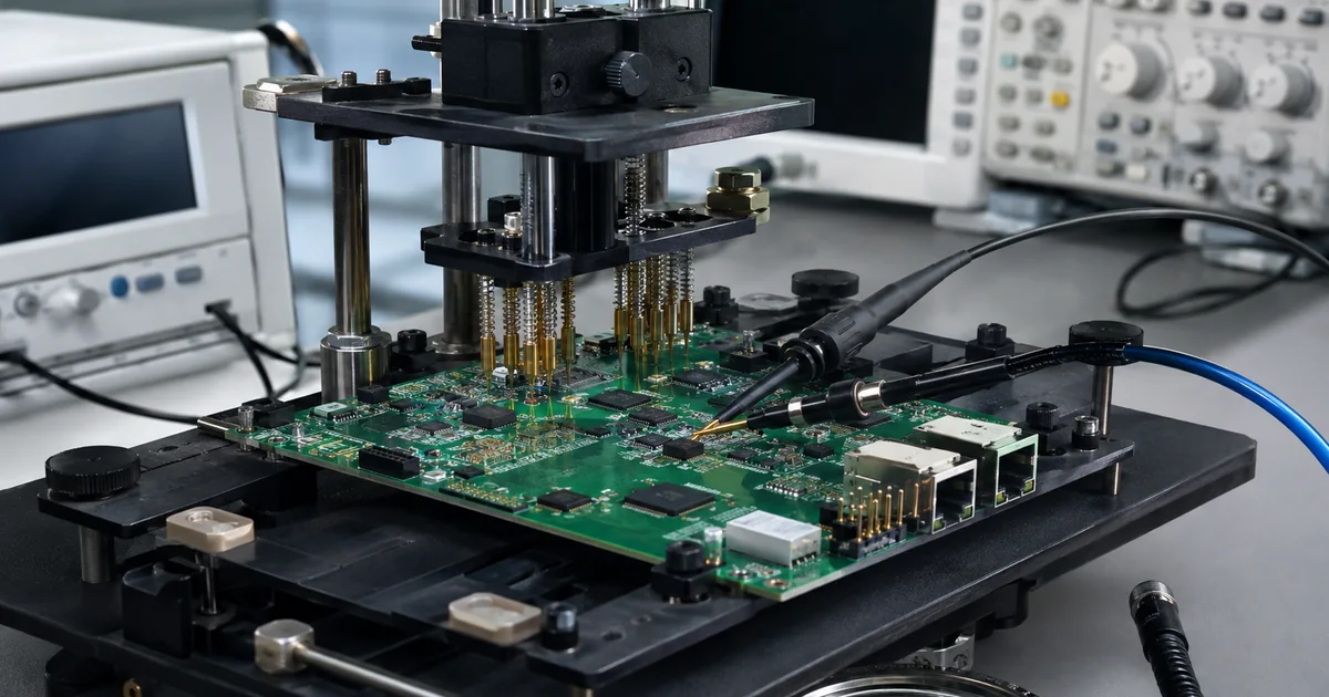
Functional testing should state inputs, operating conditions, loads, interface commands, expected outputs, tolerances, duration, and retained results. Decide who supplies the fixture and golden unit, who maintains the test software, and what happens after failure. For prototypes, diagnostic access can be more valuable than a single pass/fail light.
Build a prototype test plan from risk
- List failure modes. Use the schematic, layout, package mix, power architecture, and intended use to identify credible failures.
- Assign evidence. Choose inspection or test methods that can actually reveal each failure and define limits.
- Run and learn. Retain unit-level results, investigate representative failures, and update the next revision or repeat-build plan.
Prototype test planning questions
Does AOI replace functional testing?
No. AOI can provide repeatable evidence about visible assembly conditions, while functional testing evaluates defined electrical or product behavior. They answer different questions.
Should every prototype BGA be X-rayed?
The decision should reflect package risk, process history, access to other evidence, and the consequence of an undetected defect. If X-ray is required, agree coverage and acceptance criteria rather than requesting it as an undefined checkbox.
What is a useful prototype test deliverable?
A unit-level record linking board revision, firmware, test version, measured result, pass/fail disposition, and any rework is more useful than an untraceable summary. Photos or plots should identify the associated unit and criterion.
Related Cyrionix resources
Use the PCBA prototyping guide to place testing in the complete build flow. The assembly file checklist covers inputs needed before release.
Technical references
- IPC assembly acceptance and soldering standards
- IPC current document revision table
- KiCad fabrication and position-file documentation
Defining prototype acceptance? Review the PCB assembly testing service scope for the released prototype.