
Through-Hole PCB Assembly for Mixed-Technology Builds
Through-hole components remain relevant where the design uses connectors, terminals, relays, transformers, large capacitors, power devices or other parts whose mechanical, electrical or availability requirements do not fit an SMT-only route.
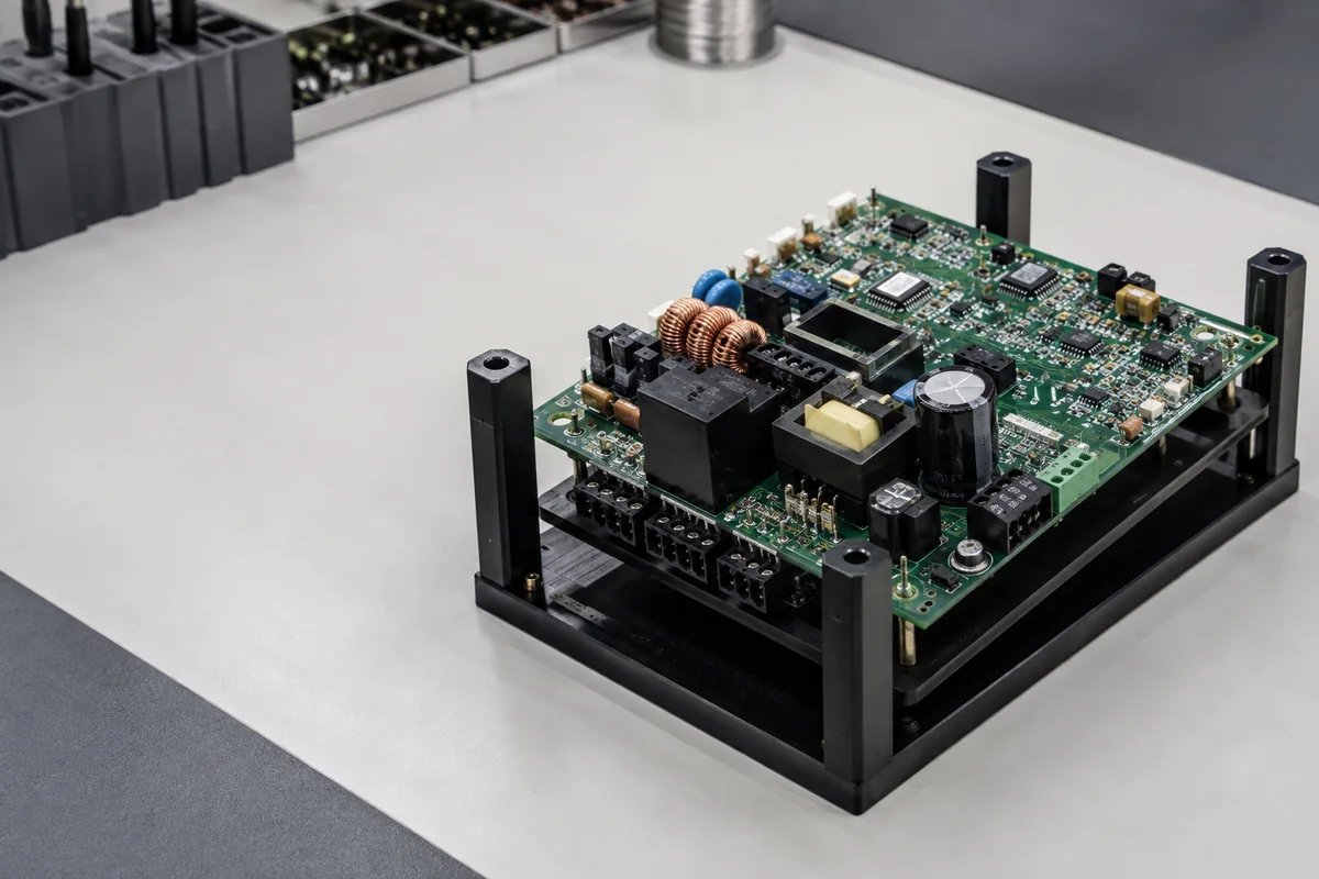
What does a through-hole PCB assembly service need to define?
A through-hole PCB assembly service must define component preparation and insertion, mechanical support, solder access, the manual, wave or selective soldering route, protection of nearby SMT parts, trimming or hardware operations, and inspection criteria. The best route depends on layout, component mix, quantity and workmanship requirements. Cyrionix confirms the process with a suitable manufacturing partner rather than assuming one method fits every board.
Through-hole, THT and PTH describe related but different things
THT usually describes components with leads inserted through holes. PTH describes the plated hole structure in the PCB. Buyers often use the terms interchangeably when requesting assembly, so drawings should define the actual component and solder requirement.
| Assembly condition | Why it matters | Process questions | Required input |
|---|---|---|---|
| Connectors and terminals | Mating force and repeated handling can load the solder joint and board | Support, seating, alignment, solder access and hardware sequence | Mechanical drawing, seating rule and critical dimensions |
| Transformers, relays and large capacitors | Mass, lead geometry, thermal demand and clearance affect handling | Insertion, retention, solder method, trimming and cleaning | Exact MPN, body/lead detail and special support notes |
| Mixed SMT/THT board | The through-hole step occurs around already placed surface-mount parts | Side sequence, bottom-side clearance, pallet or selective route | Complete population drawing and component height data |
| Odd-form or wired part | Automation and standard feeder assumptions may not apply | Forming, orientation, strain relief, hand operation and inspection | Photos, work instruction or controlled sample where needed |
| High-current or thermal part | Copper and hole design influence process and acceptance | Thermal relief, solder fill criterion and heat exposure | Design intent and applicable workmanship requirement |
Choose the soldering route from the assembled board
The available method must be confirmed with the manufacturing partner. The design, quantity and proximity of bottom-side components determine what is practical.
Useful for prototypes, odd-form parts and low quantities where access is clear and operator instructions are controlled. It is not automatically the lowest-risk choice for thermally demanding or repetitive joints.
Can process suitable through-hole populations efficiently, but bottom-side SMT, keep-outs, pallet needs, thermal mass and component restrictions must be reviewed.
Can localize solder application around mixed-technology layouts where a full wave route is unsuitable. Nozzle access, keep-out space, board support and thermal conditions still require design review.
Some boards need a combination of controlled machine and manual operations. The traveler should identify sequence, inspection and responsibility for each operation.
Prevent a mechanical part from becoming an assembly surprise
Through-hole drawings need to communicate physical intent that may not exist in the centroid file. Height, seating, orientation and hardware can affect enclosure fit as well as soldering.
Reconcile hole, lead and finished-board information
Confirm the exact component suffix, lead dimensions, PCB hole and pad design, board thickness, plating and any press-fit or special instruction. The assembler should not infer that a component fits because a generic family drawing looks similar.
Document orientation and seating
Polarized capacitors, diodes, relays, connectors and keyed devices need unambiguous orientation evidence. State whether the body must sit flush, use a controlled standoff or align to a mechanical datum. Include torque or hardware sequence only where the design requires it.
Plan mixed-technology order
SMT usually precedes the through-hole step, but the exact sequence depends on both board sides, thermal limits and solder access. Link the route to the released variant so a later DNP or connector change does not silently invalidate the process.
Inspect against a named criterion
Visible checks may cover identity, orientation, seating, lead trim and workmanship. Hole-fill or other acceptance criteria should be tied to the agreed standard and class or to an approved project rule. Inspection does not replace functional testing where product behavior must be demonstrated. See PCB assembly testing methods and limits.
What to send for a mixed SMT and through-hole build
Use photos or controlled sketches for unusual operations, but keep them revisioned with the formal assembly package.
Complete assembly view
BOM, variant/DNP rules, SMT placement data and drawings showing all through-hole and odd-form components.
Fit and support
Body height, seating, orientation, lead forming, hardware, connector datum and enclosure-critical dimensions.
Soldering constraints
Solder requirement, thermal-sensitive parts, bottom-side SMT clearance, cleaning restrictions and manual work.
Inspection and test
Workmanship basis, critical joints, sample coverage, electrical/function checks and failure disposition.
Mixed-technology scope: This service review covers boards that combine SMT and through-hole components. The quoted process route depends on the released population, access, thermal constraints, volume and acceptance requirements.
Questions that define a through-hole build
These details determine whether manual, wave or selective soldering is practical and what workmanship evidence should be quoted.
What is through-hole PCB assembly?
Through-hole assembly inserts component leads through drilled holes in the PCB and solders them to create electrical and mechanical attachment. Many modern boards combine through-hole parts with SMT devices.
When should a PCB use through-hole components?
The choice follows component availability and design needs such as connector mechanics, high current, thermal behavior, large package size or legacy parts. Through-hole is not universally stronger or better; the complete joint and board design determine performance.
Can SMT and through-hole components be assembled on the same board?
Yes. This is commonly called mixed-technology assembly. The sequence and soldering method must account for components on both sides, solder access, thermal exposure and any required pallet or manual operation.
Do you use wave soldering or selective soldering?
The method is selected and confirmed for the specific board and manufacturing partner. Layout, bottom-side SMT, quantity, nozzle or pallet access, thermal demand and workmanship requirements influence the choice.
What information is needed for odd-form components?
Provide the exact MPN, mechanical drawing, orientation, seating or standoff requirement, lead-forming instruction, hardware and any controlled photo or work instruction needed to remove ambiguity.
Prepare a mixed-technology release
Continue with the low-volume, file-package and prototype guidance relevant to THT-intensive hardware.
Define the complete mixed-technology route
Send the assembly drawings, BOM, board data, quantity and mechanical constraints for a through-hole process review.