
SMT PCB Assembly for Prototype and Low-Volume Builds
Surface-mount assembly depends on more than a placement machine. The released BOM, component packaging, stencil data, board finish, placement coordinates, polarity evidence, reflow route and inspection plan must describe the same build.
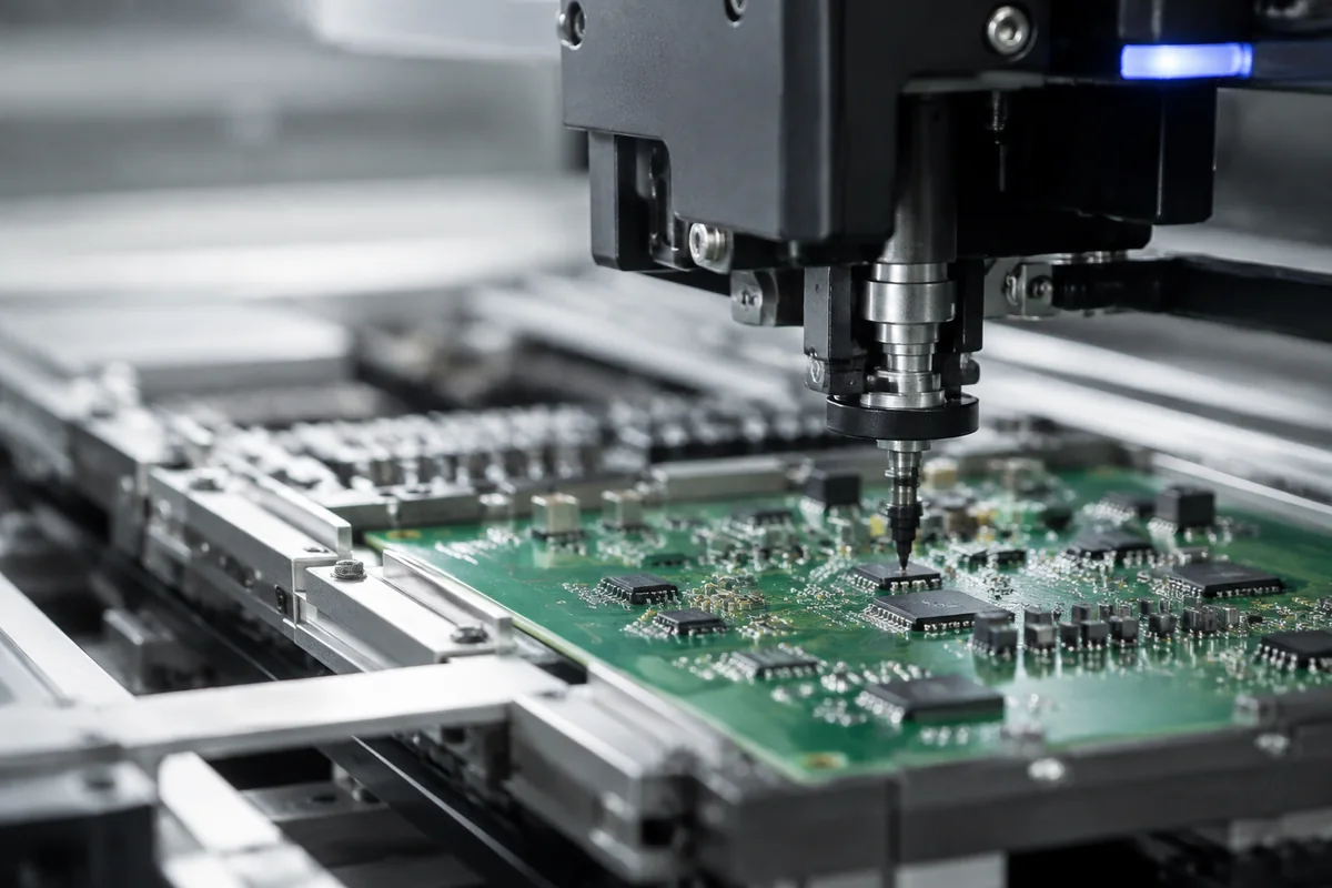
What should an SMT PCB assembly service control?
An SMT PCB assembly service should control component identity and packaging, solder-paste application, placement orientation, reflow, visible inspection and any project-specific hidden-joint or electrical verification. For prototypes and small batches, setup and engineering review can be as important as placement time. Cyrionix confirms package range, sidedness, inspection and schedule with the selected manufacturing partner before release.
Convert CAD outputs into a controlled SMT build
Every stage should have an input, a check and an owner. The sequence may vary with the board, but the decision points should remain visible.
Compare the released BOM, centroid/CPL, Gerber paste layers and assembly drawing. Resolve reference, side, origin, rotation, polarity and DNP differences before setup.
Confirm exact MPNs, approved sources, reel/cut-tape/tray packaging, quantity and attrition. Customer-supplied material must be labeled and suitable for the intended handling route.
Review paste-layer intent, aperture concerns, board support and stencil requirements against package mix and known assembly risks. Do not treat an auto-generated paste layer as a complete process instruction.
Confirm single- or double-sided sequence, component constraints and any manually placed or protected devices. Reflow profile and process choices belong to the selected manufacturing route.
Use visible inspection for identity, orientation and workmanship; define additional evidence where joints are hidden or product function must be demonstrated.
Package type changes the questions, not the standard of proof
The matrix identifies review topics. It is not a claim that every partner supports every package, pitch or inspection method.
| Design condition | Review before release | Useful evidence | Common mistake |
|---|---|---|---|
| Fine-pitch leaded device | Land pattern, paste, orientation, coplanarity and nearby access | Rendered placement check and visible inspection criteria | Using package family instead of exact orderable part |
| QFN/DFN or bottom-terminated part | Exposed pad, paste division, thermal path and voiding criteria if required | Process review and agreed hidden-joint inspection where justified | Assuming AOI can see beneath the package |
| BGA/LGA/CSP | Partner capability, storage/handling, land pattern, warpage and inspection plan | Partner confirmation and project-specific X-ray criteria | Publishing a pitch limit without checking the actual device |
| Double-sided SMT | Side sequence, mass, thermal cycles, support and later THT interaction | Assembly route linked to the released variant | Quoting two sides as if setup were unchanged |
| Moisture-sensitive material | Packaging state, exposure history and handling requirements | Incoming condition and controlled handling record as agreed | Sending loose parts without traceability or exposure data |
Setup economics matter at low quantity
For a small-batch SMT assembly, stencil preparation, feeder setup, programming, first-article checks and material packaging do not shrink in direct proportion to board quantity.
Use quantity to match the learning objective
A five-unit engineering build and a 100-unit pilot should not have identical release logic. The earlier build may prioritize diagnostic access and design feedback; the pilot needs stronger revision identity and repeatable acceptance. Review prototype PCB assembly and low-volume PCB assembly to select the lifecycle path.
Keep placement data auditable
State units and coordinate origin, include side and rotation, and reconcile every populated reference designator. A visual render can expose systematic bottom-side rotation or origin problems that pass a spreadsheet check.
Define first-article approval around meaningful risks
First-article review may include component identity, polarity, selected joints, mechanical fit, firmware or functional measurements. Name who can approve the remaining build and what happens when the evidence is inconclusive.
Select inspection for the defect question
AOI can improve repeatability for visible conditions but does not prove electrical function. X-ray can examine selected hidden-joint questions but needs interpretable criteria. The AOI versus X-ray guide describes the difference without treating either method as universal proof.
What to send for an SMT PCB assembly quote
Include the open questions. A supplier cannot price an unknown test, alternate policy or customer-supplied material route accurately.
Released board and variant
Gerber/ODB++, drill, BOM, CPL, assembly drawing, DNP rules and revision identity.
Purchasing intent
Exact MPNs, approved sources and alternates, customer-supplied lines, packaging and quantity.
Critical conditions
Single/double-sided population, lead-free or other solder requirement, sensitive parts, hand operations and depanelization.
Evidence required
Workmanship basis, inspection targets, programming, functional limits, sample coverage and report needs.
Capability gate: Package size, pitch, sidedness and inspection availability are confirmed against the actual partner and design before schedule commitment.
Questions that shape an SMT assembly quote
The answers determine setup effort, material readiness and the inspection scope needed for the released SMT design.
What is the difference between SMT and SMD assembly?
SMT describes the surface-mount technology and process; SMD describes a surface-mount device. Buyers commonly use both phrases for the service, but SMT PCB assembly is the clearer process term.
Is SMT PCB assembly economical for 10 or 20 boards?
It can be appropriate when the package mix is difficult to assemble manually or repeatability matters. Fixed stencil, setup, programming and review costs have a larger effect per board at low quantity, so compare total learning value rather than unit price alone.
Can you assemble components on both sides of the PCB?
Double-sided assembly may be available depending on the component mix and selected partner. The route must account for side sequence, thermal cycles, component mass, support and any later through-hole process.
Does AOI detect every SMT assembly defect?
No. AOI evaluates visible conditions within its programmed coverage. Hidden joints, internal electrical behavior and product function require other evidence selected for the relevant risk.
Can I provide components that are not in a standard parts library?
A partial-turnkey or consigned build can use approved customer-supplied parts when identity, quantity, packaging, traceability and handling requirements are suitable for assembly.
Resolve the next SMT build decision
Continue with the prototype, sourcing and design-file guidance that supports an executable SMT release.
Review the package before loading the line
Share the released BOM, placement data, board files, quantity and acceptance requirements for an SMT build review.