
What Files Are Needed for PCB Assembly? Gerber, BOM and CPL Explained
Prepare a complete manufacturing package that identifies the board, components, placement, assembly notes and verification requirements.
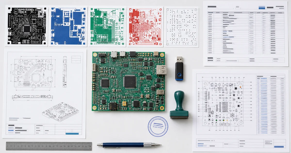
A PCB assembly package normally includes PCB fabrication data, a bill of materials, a component placement file, assembly drawings and any programming or test instructions. The exact format can vary, but every file should describe the same released revision. Missing part numbers, DNP conflicts and mismatched designators are common reasons a useful quotation is delayed.
Core file set
| File | Purpose | Check before sending |
|---|---|---|
| Gerber and drill files | Define copper, mask, legend, outline and drilled features for fabrication | Include all required layers, board outline and matching drill data |
| BOM | Identifies placed parts and purchasing requirements | Use exact MPNs, references, quantities, DNP and approved alternatives |
| CPL / centroid / position file | Lists component coordinates, rotation and board side for placement | Confirm units, origin, side and excluded footprints |
| Assembly drawing | Clarifies polarity, orientation, DNP and special handling | Match designators and revision to BOM and placement data |
| Programming package | Defines firmware and loading method | Include files, version, interface and verification step |
| Test instructions | Defines expected behavior and acceptance | Provide fixtures, connections, sequence and pass limits |
Revision-consistency check
- File names or notes identify the released revision.
- BOM and CPL reference designators use the same set.
- DNP parts are treated consistently across BOM, CPL and drawings.
- Board side and rotation conventions are confirmed.
- Panel data and single-board data are not mixed without explanation.
- Firmware and test instructions identify the intended hardware revision.
What official EDA documentation confirms
KiCad documents Gerber generation under Fabrication Outputs and explains that component placement files list footprint center positions and orientations for pick-and-place use. It also provides a Bill of Materials output. Your manufacturer may have additional naming and format requirements, so confirm the required package before release.
Useful RFQ context beyond files
- Prototype and follow-on quantities
- Consigned versus supplier-purchased parts
- Delivery country
- Target manufacturing and arrival dates
- Required standards or traceability
- Inspection, programming and test scope
KiCad 10 manufacturing package: export and verify
KiCad can generate the fabrication and placement outputs, but an export is not a released package until the team verifies revision, variant, orientation, DNP state and assembly instructions against the same baseline.
| Output | Use | Verification before release |
|---|---|---|
| Gerber and drill | Board image and drilled features | Layer set, units, origin, apertures, drill pairs and plotted revision |
| Gerber job / stack-up notes | Transfers board context | Confirm the selected fabricator accepts and interprets the data; do not rely on file presence alone |
| BOM | Part identity and fitted quantity | Exact MPN, variant/DNP state, quantity and approved-source rules |
| Position file | Pick-and-place coordinates and rotation | Origin, top/bottom convention, centroid, rotation and polarized orientation |
| Assembly drawing | Human-readable intent | Pin 1, polarity, DNP, special handling and both board sides |
| IPC-D-356 netlist | Supports bare-board checks | Exported from the released board and requested/accepted by the fabricator |
Release record: save a manifest with filename, revision, export date, source tool/version and approval owner. Compare generated files with the native design before transmitting them.
Continue your project planning
Use the related service and resource pages to turn this guidance into a reviewable manufacturing request.
Related decision guides
Use these focused resources before releasing the next assembly package.